The acoustic chamber is an essential feature of acoustic electronic targets used for shooting sport. The acoustic chamber isolates the acoustic sensors in the target frame from a range of environmental influences that would adversely affect the accuracy and reliability of the target. The potential errors are so significant that without an acoustic chamber an electronic target is effectively unsuitable for competition at any level.
The purpose of this article is to explain to potential purchasers of electronic targets how the acoustic chamber works and why it is so important, and to inform them about the serious performance issues with shot-placement products that have no acoustic chamber.
HEXTA development – what we found
Early in the development of HEXTA electronic targets we trialled prototypes without an acoustic chamber. We found that errors of up to 30 cm were possible under certain conditions through a combination of error sources. We discussed this with top shooters and they gave us the message loud and clear: errors of such magnitude are totally unacceptable, even for club-level shooting, coaching or testing. Shooting sport is all about accuracy, and no shooter will accept even the possibility that an electronic target could significantly increase their group size!
HEX Systems has always been dedicated to minimising or eliminating errors whatever the source, so there was never a question of using a design other than the acoustic chamber.
What is an acoustic chamber, and how does it work?
An acoustic chamber is the enclosed space formed inside a target frame when two rubber membranes are stretched over its front and rear faces. The acoustic sensors are mounted inside the chamber in the perimeter frame, and they detect acoustic waves propagating inside the chamber.
When a projectile penetrates the front rubber membrane, the external acoustic wave front is blocked by the membrane. As the projectile enters the chamber a new wave front is generated from the point of penetration; this wave front radiates outwards and is detected by the sensors.
Because the internal wave front has not been exposed to external environmental influences, it is not subject to the errors that they cause.
What are the major sources of error that the acoustic chamber prevents?
With open-sensor targets the projectile must impact at right angles to the target face. Any angle will cause errors of shot position.
The greater the angle, the greater the error. The error is worse at longer ranges because the projectile velocity is lower.
For example:
- HBC .308 155gr: Angle 2° causes error = 48 mm at 1,000 yards
- Sierra .223 80gr: Angle 5° causes error = 220 mm at 1,000 yards
The angle may be caused by tilting of the target (static or dynamic), by downward trajectory of the projectile, by the shooter’s position on the mound, or any combination of these.
Target tilt and projectile trajectory cause vertical errors, while the position on the mound, or horizontal misalignment of the target, cause horizontal errors.
Target tilting. It is very common for targets to be installed off-the-vertical (static tilt), or to move fore-and-aft in the wind (dynamic tilt). A fore-and-aft target movement of ± 5° causes a vertical shift in measured shot position of 24 cm (=1 MoA) at 1,000 yards(HBC .308 155gr). Note that targets can twist in the wind, causing horizontal errors.
Even in gentle breezes targets move due to slack in the machinery or target flexibility. A movement of only ± 2° causes a dynamic error (that is, an error which may vary from shot to shot) of about 4.8 cm at 1,000 yards (HBC .308 155gr).
And even when the target is rigidly mounted, if the target is not set vertical there will be a static error (that is, an error which does not vary from shot to shot). If multiple targets are set at different angles you may notice a shift in your elevation when moving between targets.
By the same principle, the downward trajectory of the projectile impacting the target causes a vertical upward shift. Similarly, the shooter’s position across the mound causes a lateral shift. At 300 m a shift of 2 m across the mound results in an error of about 0.3 cm in reported shot position.
The graphs below plots the theoretical error versus angle of impact and range distance. The data is based on an HBC .308 155gr and Sierra .223 80gr, each with muzzle velocity 3,000 fps.
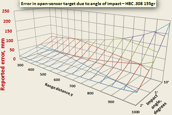
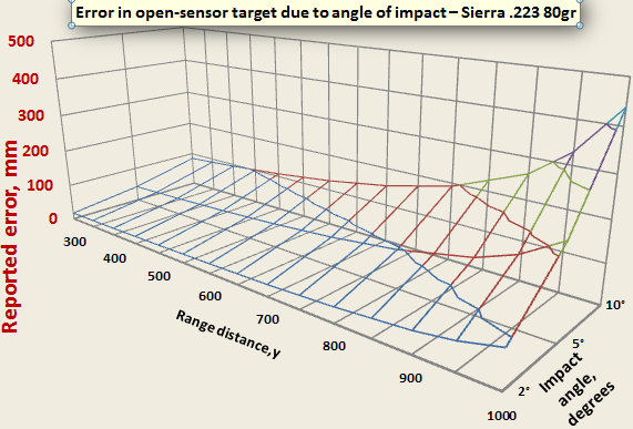
The table below shows the calculated error data used in the above graph.
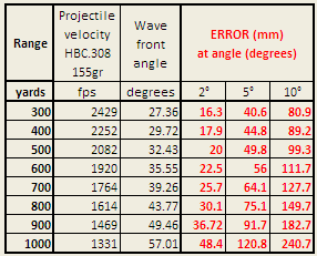 |
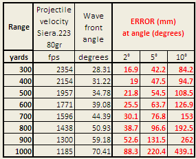 |
For the calculations that generated these figures, refer to Appendix A.
Additionally, diagonal twisting/warping of the target frame will cause errors because all sensors no longer lie in a single, flat plane. The principle is the same as in the tilting effect.
For example, a 5 cm diagonal warp in the target frame will cause an error of 2.1 cm, at 900 m and 1352 fps. The derivations follow the same principles as shown in Appendix A.
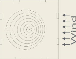
Without an acoustic chamber, cross-winds at the target face cause a horizontal shift of measured shot position is due to the Doppler Effect in the direction of the wind. You can expect a shift of approximately 3 cm in a 10 m/s crosswind. In other words, the target error magnifies the windage effect.
And remember, it’s the wind at the target face that matters. So a local gust at the target will cause an error even if the flags uprange are still.
Now consider a real situation. You’re shooting in windy conditions and you’ve just dropped a shot at three o’clock. Was it due to the wind deflecting the projectile? Was it wind-induced target error? Or was it both? And if so, how much was due to target error? If the target has no acoustic chamber, you’ll never know.
Update: The practical test were performed and results are available HERE
-
Unresolvable shots due to shots on nearby targets
If the sensors are not isolated from the ambient air, they are much more likely to pick up acoustic waves from shots on adjacent targets or any another external noises. If a nearby shot is fired at around the same time as yours, the target may be unable to resolve your shot. This effect is more significant at longer ranges where projectile velocities and wave front energy are lower.
Note. Readers may be familiar with the problem of “unexplained misses” on conventional 4-sensor acoustic chamber targets. A target without an acoustic chamber is even more susceptible, for the reasons stated above. In contrast, HEXTA targets with 8-sensor error-minimisation technology have vastly reduced occurrence of lost shots compared with conventional targets.
Appendix A – Angle of impact – Detailed explanation
A.1 Basic principles of acoustic position sensing
As a supersonic projectile travels through air it generates a conical acoustic wave, travelling at the speed of sound.
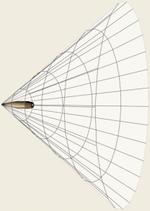
The shape of the cone varies with projectile velocity. At high velocities the cone is narrow and pointed; at lower velocities it is flatter.
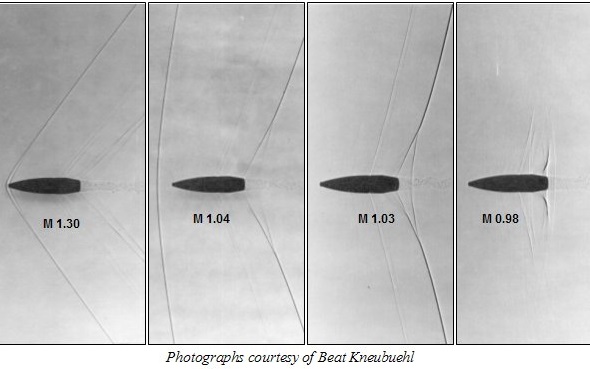
The angle of the conical acoustic wave is determined by the formula (click for more information)![]() where μ is the angle between the trajectory and the wave front, and M is the projectile velocity/speed of sound ratio, or Mach number.
where μ is the angle between the trajectory and the wave front, and M is the projectile velocity/speed of sound ratio, or Mach number.
The derivation of the formula is described in the book Flow of a compressible fluid .
The projectile velocities for the ranges 300 – 1000 yards for projectile HBC.308 155 gr and Sierra .223 80 gr were calculated using the JBM ballistics calculator. The velocity vs range distance data can be found here for HBC .308 and here for Sierra .223.
Acoustic position sensing is achieved by the following process:
- Each sensor detects the onset of the acoustic wave front emanating from the projectile;
- The target processor accurately timestamps the triggering of each sensor and calculates the time interval between each;
- With these time intervals, and knowing the physical locations of all the sensors, the processor estimates the impact position.
The calculation is based on the assumption that all sensors lie in a single plane which is perpendicular to the trajectory of the projectile.
A.2 The condition where the trajectory is not perpendicular to the plane of the sensors
If the trajectory is not perpendicular to the plane of the sensors, the relative timing of sensor triggering will be affected. The following image shows two trajectories – one perpendicular to the sensor plane, the other at a downward angle. Both trajectories impact the very centre of the target.
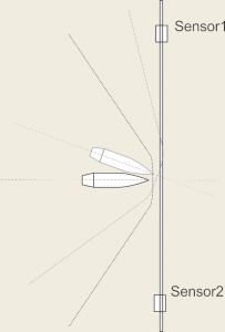
In the case of the perpendicular trajectory both sensors will be triggered (i.e.: detect the wave front) at the same time. Because there is no time difference between the two triggers the processor will determine an impact point midway between the sensors, i.e.: at the centre of the target.
In the case of the angled trajectory it is apparent that the top side of the cone will reach the upper sensor before the bottom side reaches the lower sensor. Because the processor assumes a perpendicular trajectory, it will calculate an impact point that is closer to the upper sensor and further from the lower sensor; i.e.: a vertical error in the upward direction.
The figures below illustrate how this error can be quantified. In the figure we are looking on either a vertical or horizontal section through the target. Note that in the case where there is an angle of impact in both planes, the diagonal error will be the vector sum of the errors in the two orthogonal planes.
In this example the sensors are spaced 1800 mm apart, the projectile velocity is 1614 fps and the angle of the wave front is 43.8°. The speed of sound is 340.3 m/s.
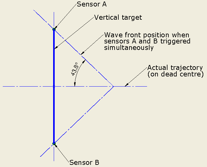 Image 1 – Target vertical, impact position on dead centre
Image 1 shows a projectile impact on the dead centre of the target. The projectile, traveling from left to right, has passed through the target. The image shows the moment when the wave front contacts sensors A and B simultaneously. The processor will correctly determine the shot position on dead centre of target.
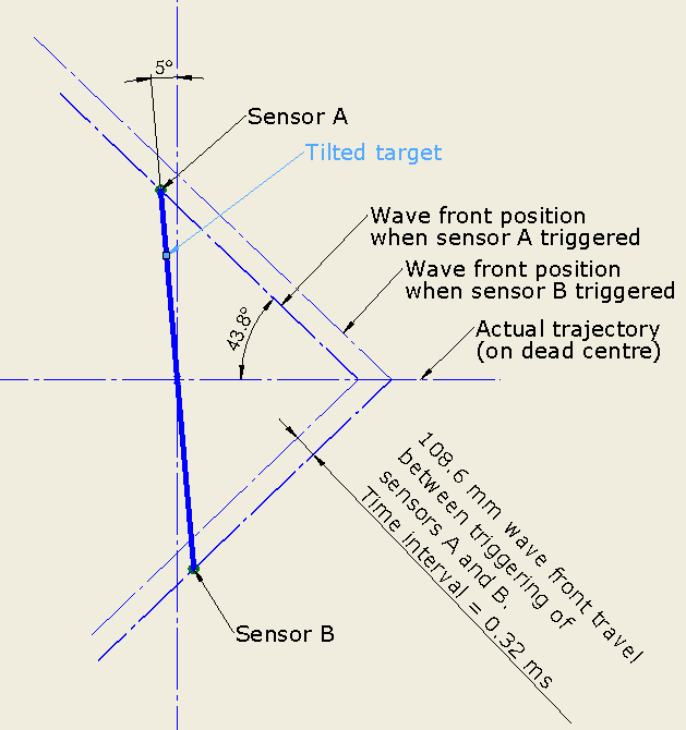
Image 2 – Target angle 5°, impact position on dead centre
In Image 2 the target is angled at 5°. Two wave front cones are shown – the first is at the moment it contacts sensor A, the second at the moment it contacts sensor B. There is a time interval of 0.32 ms between these two events.
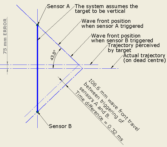
Image 3 – Impact per Image 2 as perceived by the system
Image 3 shows how the target processor perceives the shot from Image 2. Because it assumes the target is vertical, it uses the measured time interval of 0.32 ms to determine a shot position 75 mm higher than its actual position. The magnitude of the error is 75 mm.
Copyright © HEX Systems 2015
Leave a Reply